

On this page
- Rotary dryer diagram: parts and their functions
- What sets the size
- Worked example: sizing from throughput
- Heat transfer check
- Design details that matter
- Operating variables
- What I see in plants
- Frequently asked questions
- What fill level should a rotary dryer have?
- How do I change retention time?
- Why does my rotary dryer carry dust out?
- Rotary dryer or fluid bed dryer?
- What is a good L/D ratio?
- Sources and further reading
- More on Industrial Dryers
Short answer: Size a rotary dryer shell from the hold-up the product needs: throughput multiplied by retention time gives the mass in the drum, bulk density turns that into volume, and a fill level of about 8 to 15 per cent of the shell volume gives the shell size. Then choose length-to-diameter ratio, rotational speed (from a peripheral speed), slope and gas velocity. Retention time and fill level matter more than shell size alone, and the figures below are a first estimate to check a supplier’s offer.
Rotary dryer diagram: parts and their functions
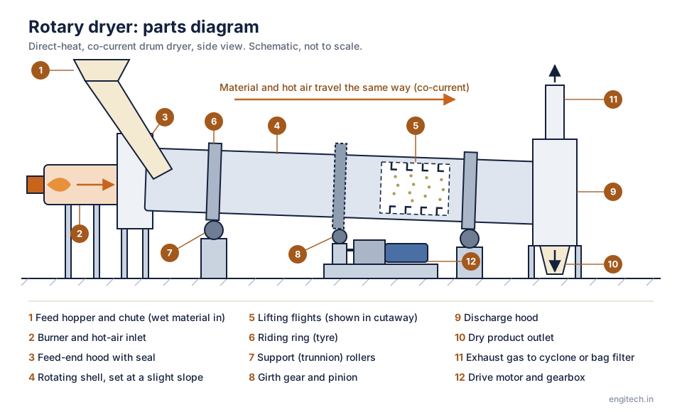
| No. | Part | What it does |
|---|---|---|
| 1 | Feed hopper and chute | Delivers the wet material into the raised end of the shell. |
| 2 | Burner and hot-air inlet | Supplies the hot gas that carries heat to the material. In a co-current dryer it enters at the feed end. |
| 3 | Feed-end hood with seal | Stationary housing that closes the gap between the fixed ducting and the rotating shell and limits air leakage. |
| 4 | Rotating shell | The inclined drum. Its rotation and slight slope move the material steadily toward the discharge end. |
| 5 | Lifting flights | Plates fixed inside the shell that lift the material and shower it through the hot gas stream. |
| 6 | Riding ring (tyre) | Steel ring around the shell that transfers its weight to the support rollers. |
| 7 | Support (trunnion) rollers | Carry the riding rings and let the shell turn. Thrust rollers, not shown, stop the shell sliding downhill. |
| 8 | Girth gear and pinion | A large ring gear on the shell, driven by a small pinion, turns the drum. |
| 9 | Discharge hood | Stationary housing at the lower end where the dried solids and the exhaust gas separate. |
| 10 | Dry product outlet | Dried material leaves by gravity at the bottom of the hood. |
| 11 | Exhaust gas outlet | Moist gas leaves at the top and goes to a cyclone or bag filter, which recovers the dust it carries. |
| 12 | Drive motor and gearbox | Turn the pinion at the low speed the drum needs. |
Download this diagram (SVG)Schematic for learning. Real machines vary by maker and duty.
When buyers compare rotary dryer quotations, the diameter and length look like the whole story. In my conversations with dryer engineers, the design depends much more on how long the material must stay in the drum and how it moves along it. This guide sets out the sizing logic with a worked example, as a companion to rotary dryer troubleshooting, the drum and rotary dryer working principle and residence time distribution in dryers.
What sets the size
| Parameter | Typical range | Why it matters |
|---|---|---|
| Retention time | 10 to 60 minutes (set by drying tests) | Time for heat and mass transfer to reach the target moisture |
| Fill (loading) level | About 8 to 15 per cent of the shell volume | Too high: poor contact and poor lifting; too low: wasted shell volume |
| Length to diameter ratio (L/D) | About 4 to 10 | Controls contact time and gas flow pattern |
| Peripheral speed | About 0.2 to 0.5 m/s (up to about 1 m/s for some products) | Determines how well flights cascade the material |
| Slope | About 0.5 to 5 per cent (a fraction of a degree to about 3 degrees) | Moves the material forward and shortens or lengthens retention time |
| Gas velocity | About 1 to 3 m/s (lower for fine, dusty material) | Too high carries dust out with the exhaust |
| Flights | Lifting, cascading, designed for the material | Provide the curtain of falling particles that exchanges heat with the gas |
Worked example: sizing from throughput
A rotary dryer must handle 5,000 kg/h of wet feed, with a retention time of 30 minutes from tests. The material has an average bulk density of 700 kg/m³ and the design fill level is 10 per cent.
- Hold-up = throughput × time = 5,000 × 0.5 h = 2,500 kg (using the average of wet and dry masses, for simplicity).
- Material volume = 2,500 / 700 = 3.57 m³.
- Shell volume = 3.57 / 0.10 = 35.7 m³.
- With a diameter D = 2.0 m (cross-section 3.14 m²): length L = 35.7 / 3.14 = 11.4 m. L/D = 11.4 / 2.0 = 5.7, in the usual range.
- Rotational speed: choose a peripheral speed of 0.35 m/s. N = v / (π D) = 0.35 / (π × 2.0) = 0.0557 rev/s = 3.3 rev/min.
- Gas flow check: suppose the dryer needs 25,000 m³/h (6.9 m³/s) of hot gas. With about 85 per cent of the cross-section free of material, free area ≈ 0.85 × 3.14 = 2.67 m²; gas velocity = 6.9 / 2.67 = 2.6 m/s, within the range for granular material; for fine dusty material it would be too high and a larger diameter or lower air flow would be needed.
Now see what a different choice does. A smaller shell at 1.6 m diameter and 12 m long has volume π/4 × 1.6² × 12 = 24.1 m³; at 3.57 m³ of material the fill is 3.57 / 24.1 = 14.8 per cent, at the top of the range, and retention time would be shorter if the material moves faster along a steeper slope. The gas velocity in a 1.6 m drum rises to 6.9 / (0.85 × 2.01) = 4.0 m/s, likely to carry out fines. A quotation for a shell much smaller than the estimate deserves a question about the retention time and the heat balance. The values here are first estimates; the supplier’s design must be based on tests and the thermal balance. See indirect dryer sizing for the energy balance logic.
Heat transfer check
A direct rotary dryer exchanges heat between hot gas and the falling material. The heat transfer volumetric coefficient, Ua, is typically in the range of 100 to 300 W/m³·K for common materials. Required volume V = Q / (Ua × ΔT_lm). For 556 kg/h of water evaporated (heat ≈ 1.47 GJ/h = 407 kW) with a log mean temperature difference of 90 K and Ua of 150 W/m³·K: V = 407,000 / (150 × 90) = 30.1 m³. This is close to the 35.7 m³ from retention time, so both views agree; if the heat transfer volume came out larger than the retention volume, the heat transfer would govern the size. Use the larger of the two, as the supplier should.
Design details that matter
- Flights: lifting flights near the feed end, cascading flights in the middle, and less aggressive ones near the discharge for fragile or sticky products.
- Feed and discharge arrangement: controlled feeding by screw or rotary valve; a discharge housing with seals to limit air leakage.
- Co-current or counter-current: co-current (gas and solid in the same direction) is gentler and better for heat-sensitive products; counter-current is more energy-efficient for products that tolerate hot product exit temperatures.
- Drive and support: riding rings, trunnion rollers and a girth gear and pinion; alignment and lubrication are critical; see gearbox failure causes.
- Seals: inlet and outlet seals control air leakage and dust.
- Exhaust: cyclone and bag filter, with condensation control; see dryer exhaust dew point and condensation.
Operating variables
- Feed rate and moisture: higher moisture needs more time or more heat.
- Rotational speed: faster speed shortens retention time slightly and increases cascading.
- Slope (fixed in most dryers, adjustable in some).
- Inlet and outlet gas temperature: set by product limits and efficiency; see hot air generation for dryers.
- Gas flow: balance heat supply against dust carry-over.
What I see in plants
Rotary dryers that run well have flights and speed settings tuned for the product, a stable feed and a good record of outlet temperature and moisture. Dryers that disappoint are often fed with material wetter or stickier than designed, or run at a speed that makes the load surge. A tracer test, as described in the residence time guide, shows the real retention time and its spread. When replacing a dryer, share your feed variations and tests with the supplier. A dryer designed for the average case fails on the worst day.
Free tools for this topic: Dryer selection tool · Dryer evaporation, heat and fuel calculator · all free engineering tools
See it in 3D
Frequently asked questions
What fill level should a rotary dryer have?
Typically about 8 to 15 per cent of the shell volume, depending on the product and flight design.
How do I change retention time?
By changing speed, slope (if adjustable), feed rate or the flights; larger changes need a different shell.
Why does my rotary dryer carry dust out?
Gas velocity too high for the particle size, or too many fines; reduce air flow, increase diameter or use a different flight design.
Rotary dryer or fluid bed dryer?
Rotary dryers handle coarse, lumpy and variable materials well; fluid beds suit uniform granules and powders with tight control.
What is a good L/D ratio?
About 4 to 10; the design depends on the retention time and heat transfer needs.
Sources and further reading
For standards, data and independent guidance on this topic, see US Department of Energy process heating resources (industrial heating and drying efficiency), The Engineering ToolBox (engineering reference data and calculators), Bureau of Energy Efficiency (energy audit and efficiency programmes in India) and Bureau of Indian Standards (Indian standards catalogue). Always check the current edition and your site conditions before applying any figure.
Related reading: Indirect Dryer Sizing: Heat Transfer Area from a Mass and Energy Balance; Residence Time Distribution in Dryers: Tracer Tests and Tanks in Series; Vacuum Drying Basics: Pressure, Boiling Point and Drying Time; Hot Air Generation for Dryers: Direct-Fired, Indirect and Electric Compared.
This article is general information from my experience with dryers and is not a design. Ranges for fill, speed, velocity and Ua are typical; the figures in the example are assumed. A supplier’s design based on tests governs.
Plant steam & instrumentation check: If your rotary dryer feeds an indirect steam coil or preheater, check actual latent heat at header pressure in our Saturated Steam Table & Calculator rather than assuming 4 bar and 10 bar behave the same. For exhaust hood temperature transmitters and baghouse differential-pressure loops feeding the PLC, verify 4–20 mA raw counts with the 4–20 mA Scaling & PLC Raw Count Calculator.
Free tool for this topic
Industrial Dryer Evaporation, Heat & Fuel CalculatorWater evaporation, product output, heat load and fuel or steam consumption for spray, rotary, flash, fluid-bed and paddle dryers. Industrial DryersSludge Drying Economics: Cost per Tonne of Water Evaporated
 Industrial DryersFlash Dryer: The Ultimate Guide to Efficient Industrial Drying
 Industrial DryersRotary Dryer Diagram: Components and How It Works
 Industrial DryersComprehensive Guide to Sludge Dryer Manufacturers
 Industrial DryersSpray Dried Dispersion: Enhance Drug Solubility
 Industrial DryersHot Air Generation for Dryers: Direct-Fired, Indirect and Electric Compared