

On this page
- Centrifugal pump diagram: parts and their functions
- Before you touch anything: three questions
- Symptom guide at a glance
- Step 1: Check the suction side first
- Step 2: Work out whether you have cavitation
- Worked example
- Step 3: Compare the pump to the system it is working in
- Speed changes and what they do
- Step 4: Mechanical checks
- What I hear on the factory floor
- A field checklist you can print
- When to repair, and when to re-select
- Go deeper: the full guide series
- Frequently asked questions
- How do I know if my pump is cavitating or just drawing air?
- Can I fix cavitation by throttling the discharge valve?
- Why does my pump motor trip on overload only some days?
- How much vibration is acceptable?
- How often should wear rings be checked?
- Is it better to repair or replace an old pump?
- Sources and further reading
- Related guides
- More on Pumps, Valves and Piping
Short answer: when a centrifugal pump misbehaves, work from the suction side to the discharge side, and from cheap checks to expensive ones. Low flow, noise, vibration, hot bearings and leaking seals each have a short list of usual causes, and most of them come back to four things: not enough suction head, air in the liquid, a system that no longer matches the pump, or a pump that has worn out of its original clearances.
Centrifugal pump diagram: parts and their functions
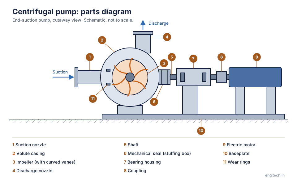
| No. | Part | What it does |
|---|---|---|
| 1 | Suction nozzle | Where the liquid enters, along the axis of the shaft. |
| 2 | Volute casing | The spiral-shaped casing. Its widening passage slows the liquid and turns its speed into pressure. |
| 3 | Impeller | The rotating wheel with curved vanes. It throws the liquid outward and gives it speed. |
| 4 | Discharge nozzle | Where the pressurised liquid leaves the casing. |
| 5 | Shaft | Transmits the torque from the motor to the impeller. |
| 6 | Mechanical seal | Seals the point where the shaft leaves the casing, so the liquid does not leak along the shaft. Some pumps use gland packing instead. |
| 7 | Bearing housing | Holds the bearings that support the shaft and take the loads from the impeller. |
| 8 | Coupling | Connects the pump shaft to the motor shaft and allows for small misalignment. |
| 9 | Electric motor | Drives the pump. |
| 10 | Baseplate | A rigid frame that keeps the pump and the motor aligned. |
| 11 | Wear rings | Replaceable rings that keep a small clearance between the impeller and the casing. They limit leakage from the discharge side back to the suction side and can be replaced as they wear. |
Download this diagram (SVG)Schematic for learning. Real machines vary by maker and duty.
I spend most of my week inside factories, talking to plant owners, maintenance heads and the engineers who run the pumps every shift. The pattern repeats from plant to plant. A pump is blamed for a problem that sits in the pipework, or the pump is replaced when a valve was half closed. The order of checks below is the one that wastes the least of everyone’s time.
Before you touch anything: three questions
- Did it ever work properly? A pump that never reached its duty point points to selection or installation. A pump that worked for two years and then dropped off points to wear, fouling or a changed system.
- What changed? New liquid, new temperature, a new tank level, a valve replaced, a strainer added, a different operator. Ask the shift operators, not only the maintenance record. In my experience the operators usually know the answer before anyone opens a file.
- What do the gauges say? Suction pressure, discharge pressure, motor current. These three readings settle more arguments than any theory.
Symptom guide at a glance
| Symptom | Most likely causes (check in this order) |
|---|---|
| No flow at all | Not primed; wrong rotation; closed suction or discharge valve; broken shaft or coupling; blocked impeller |
| Flow below rated | Partly closed valve; clogged strainer; air in suction; worn wear rings; impeller trimmed or fouled; system head higher than designed; low speed |
| Crackling or “gravel” noise | Cavitation (NPSH available too low); operating far from best efficiency point |
| High vibration | Misalignment; unbalanced or damaged impeller; loose base or pipe strain; bearing wear; cavitation; running at very low flow |
| Motor overloads | Flow too high (system head lower than designed); liquid heavier or thicker than design; rubbing parts; wrong voltage or a single-phasing fault |
| Hot bearings | Too much or too little lubricant; misalignment; contaminated oil; excess axial thrust |
| Leaking seal | Dry running; shaft deflection; poor flush plan; wrong seal materials; vibration. See our mechanical seal failure analysis |
| Pump loses prime | Air leak on suction side; vortex at the tank; foot valve leaking; suction lift too high |
Step 1: Check the suction side first
Most pump problems start before the liquid reaches the impeller. Look for a closed or partly closed suction valve, a choked strainer, a suction line that is too small or too long, an elbow right at the pump inlet, and a tank level that is lower than the design level. A vacuum gauge on the suction line, if one is fitted, tells you a lot. A reading that is far more negative than the design figure means the pump is starving.
Air is the other suction-side culprit. It enters through a loose flange, a worn gland on a valve stem, a cracked suction hose, or a vortex forming at the tank outlet when the submergence is too small. Air makes the pump noisy and the flow erratic, and it often looks like cavitation. One way to separate them: air problems usually come and go with changes in tank level and valve position, while true cavitation follows the flow rate and the liquid temperature.
Step 2: Work out whether you have cavitation
Cavitation happens when the pressure at the impeller eye falls below the vapour pressure of the liquid, so small vapour bubbles form and then collapse as the liquid moves into higher pressure. The result is noise like gravel in the casing, vibration, falling head, and pitting on the impeller vanes over time.
The test is simple (our NPSH calculator does the arithmetic): the NPSH available from your system must be higher than the NPSH required by the pump at the operating flow, with a margin. NPSH available is:
NPSHa = (Patm − Pvapour) / (ρ × g) + hstatic − hfriction
Worked example
A pump draws water at 30 °C from an open tank. The pump centreline sits 2 m above the tank water level, and the suction line loses 0.8 m to friction and fittings.
- Atmospheric pressure at sea level: 101.3 kPa
- Vapour pressure of water at 30 °C: about 4.2 kPa
- Density: about 996 kg/m³
Pressure term = (101.3 − 4.2) × 1000 / (996 × 9.81) = 9.94 m. Then NPSHa = 9.94 − 2.0 − 0.8 = 7.14 m.
If the pump curve shows an NPSH required of 6.5 m at the duty flow, the margin is only 0.64 m. That is too thin. A common working rule is to keep at least 0.5 to 1 m of margin, or more for high-energy pumps and for liquids near their boiling point. Fix it by lowering the pump or raising the tank level, shortening or enlarging the suction pipe, or cooling the liquid. Throttling the suction valve to reduce flow is not a fix. It reduces NPSHa further.
At higher altitude or higher liquid temperature, the numbers get worse quickly. A plant at 1,000 m above sea level has roughly 10 kPa less atmospheric pressure to work with. Hot condensate or hot process liquid can leave almost no margin at all. For the head side of this calculation, see how to calculate total dynamic head.
Step 3: Compare the pump to the system it is working in
A pump always runs where its curve crosses the system curve. If the flow is wrong, one of the two curves is not what you think it is.
- Flow too low, discharge pressure high: the system head is higher than designed. Look for a partly closed discharge valve, a fouled heat exchanger, a blocked filter, or a pipe that has scaled up.
- Flow too low, discharge pressure low: the pump itself is the problem. Worn wear rings, a damaged or fouled impeller, low speed, or air ingestion.
- Flow too high, motor overloaded: system head is lower than designed. A valve is wide open, or a pipe is open to atmosphere somewhere it should not be. Throttle the discharge valve, or trim the impeller.
Motor current is a quick guide. For a given pump, current rises with flow. Compare the reading with the motor nameplate and the pump’s power curve before you decide anything.
Speed changes and what they do
The affinity laws say flow varies with speed, head with speed squared and power with speed cubed. If you slow a pump to 80% speed, flow falls to about 80%, head to about 64%, and power to about 51%. This is why a variable frequency drive is such an effective energy saver on a pump that spends most of its time at part load, and why a throttling valve wastes so much. The US Department of Energy pump systems guidance describes this in detail.
One caution I give every plant that fits a drive: do not run the pump so slowly that it sits near or below its minimum stable flow. Low-flow operation causes recirculation inside the impeller, noise and shaft deflection. Read our note on minimum continuous stable flow before setting a lower speed limit.
To see what a speed or trim change does to power, use the pump affinity laws calculator and the pump power calculator.
Step 4: Mechanical checks
- Rotation. After any motor work, confirm the direction against the arrow on the casing. A reversed pump still delivers some flow, which is why this is missed.
- Alignment and pipe strain. Disconnect the pipe flanges and see whether the alignment changes. If it does, the pipework is pulling on the casing.
- Wear ring clearance. As clearance opens up, more liquid leaks back from discharge to suction. Efficiency and flow fall. Compare with the manufacturer’s clearance table and replace the rings, not the whole pump.
- Impeller condition. Check for blockage, erosion, pitting or a loose key. Pitting on the back of the vanes near the eye is a classic cavitation signature.
- Bearings and lubrication. Use the right grade, the right quantity, and clean oil. Over-greasing is as common a cause of overheating as under-greasing.
- Foundation. A cracked or loose baseplate and soft-foot give vibration that looks like a pump defect.
What I hear on the factory floor
Walking through plants in different industries, a few themes come up again and again in conversations with maintenance teams and owners.
- The pump was selected for a duty that no longer exists. Production grew, a process changed, or a product was added. The original pump now works far from its best efficiency point and nobody has revisited the selection.
- Suction piping gets added to, never simplified. Extra elbows, a strainer someone fitted for protection, a smaller reducer. Each one takes a little NPSH, and together they push the pump into cavitation.
- Spare parts are bought on price. Seals and wear rings in the wrong material fail early, and the pump gets blamed.
- There is no baseline. Nobody recorded suction pressure, discharge pressure and current when the pump was healthy, so nobody can say how far it has drifted. Taking these three readings once a month and writing them down is the cheapest reliability programme I know of.
When I talk to owners about this, the point I come back to is that the pump is rarely the root cause. It is usually the first thing in the system to show the symptom.
A field checklist you can print
- Record suction pressure, discharge pressure, and motor current.
- Confirm valve positions, strainer condition and tank level.
- Listen: gravel noise means cavitation, a rhythmic knock means a mechanical fault, a hiss means air or recirculation.
- Calculate NPSHa with today’s liquid temperature and level.
- Compare the operating point to the pump curve.
- Only then open the pump.
When to repair, and when to re-select
If the pump is within about 10 to 15 per cent of its original performance after new wear rings and a rebuilt impeller, repair is almost always worthwhile. If the duty has changed substantially, or the pump runs below about 60 per cent of its best efficiency flow most of the time, repairing it only restores a pump that was wrong for the job. In that case, ask your supplier for a re-selection with the real operating data. To prepare a clean enquiry, use our RFQ builder. For terms like NPSH, best efficiency point and cavitation, see the engineering glossary.
Go deeper: the full guide series
Each article below takes one pump problem or decision and works it through with numbers.
- Pump Not Delivering Rated Flow: Nine Causes to Check in Order
- Why a Centrifugal Pump Loses Prime and How to Stop It
- Pump Vibration: Telling Cavitation, Misalignment and Bearing Wear Apart
- How to Read a Pump Performance Curve With a Worked Duty Point
- Pump Overheating at Low Flow: Minimum Flow Explained With Numbers
- Gland Packing or Mechanical Seal: Cost, Leakage and When to Switch
- Pump Bearing Failures: What Temperature, Noise and Oil Are Telling You
- Pump Shaft Alignment: Laser or Dial Gauge, Tolerances and Soft Foot
- Suction Piping Mistakes That Damage Pumps
- Sizing a Pump Motor: Margin, Service Factor and Starting Method
- Pump Start-Up and Shutdown Checklist for Operators
- Pump Efficiency Test: Measuring Duty Point With Gauges and a Clamp-On Meter
- Pump Materials for Common Fluids: Cast Iron, SS 316, Duplex and Rubber
- Chemical Dosing Pumps: Selection and the Failures to Expect
- Horizontal or Vertical Pump Installation: Footprint, Maintenance and NPSH
- Spare Parts for Pumps: What to Stock for a Three-Year Plan
- Pump Energy Savings: Five Changes Ranked by Payback
- Commissioning a New Pump Line: Flushing, Hydrotest and First Run
- Pump RFQ: Ten Items Every Supplier Needs From You
Free tools for this topic: Pump power calculator · Pump affinity laws calculator · Equipment fault finder · all free engineering tools
Frequently asked questions
How do I know if my pump is cavitating or just drawing air?
Cavitation follows flow rate and liquid temperature: it gets worse as you open the discharge valve or as the liquid warms. Air ingestion follows tank level and suction connections. A suction-side leak test with the pump stopped, or a vacuum test, will confirm air.
Can I fix cavitation by throttling the discharge valve?
Sometimes, because lower flow lowers the NPSH required. It also moves the pump away from its best efficiency point and wastes energy. Fixing the suction conditions is the correct answer.
Why does my pump motor trip on overload only some days?
Check the liquid. A change in density, viscosity or temperature changes the power needed. Also check supply voltage and whether the system head drops when another line is opened.
How much vibration is acceptable?
Acceptance depends on pump type, power and speed. Standards such as ISO 10816 and ISO 20816 and the pump manufacturer’s limits apply. Trend the reading over time. A rising trend matters more than one number.
How often should wear rings be checked?
Inspect at every scheduled overhaul, and sooner if flow or head has dropped by around 5 to 10 per cent at the same operating point.
Is it better to repair or replace an old pump?
Repair if the casing is sound and the duty has not changed. Replace or re-select if the duty has changed, if the casing is corroded or cracked, or if the energy cost over a year is significant compared with the price of a better-matched pump.
This guide is general engineering information. Always follow the pump manufacturer’s manual and your plant’s safety procedures before opening or isolating any equipment.
Sources and further reading
For standards, data and independent guidance on this topic, see Hydraulic Institute (pump standards and user guidance), American Petroleum Institute (pump and seal standards) and The Engineering ToolBox (engineering reference data and calculators). Always check the current edition and your site conditions before applying any figure.
Free tool for this topic
Pump Power & Motor Size CalculatorHydraulic power, shaft power and recommended motor rating for centrifugal pumps from flow, head, density and efficiency. Pumps, Valves and PipingSelf-Priming Centrifugal Pumps: Working Principles & Priming Time Math
 Pumps, Valves and PipingPumps in Parallel vs Series: Sizing Calculations & Operating Point Math
 Pumps, Valves and PipingOrifice Plate Flow Meter Sizing: ISO 5167 Calculation & Beta Ratio
 Pumps, Valves and PipingPipe Fitting Equivalent Length & Resistance Coefficient K-Factor Calculation
 Pumps, Valves and PipingIndustrial Piping Procurement & MTO: Material Requisitions, Piping Classes & ITP
 Pumps, Valves and PipingPump Minimum Continuous Stable Flow (MCSF): Thermal Rise & Recirculation Math
